ARDUINO PROGRAMMING - Input and Output Devices
- Alex Neo
- Nov 30, 2021
- 7 min read

Arduino Programming is a form of coding that allows endless possibilities. Using electrical signals, inputs such as light, temperature, physical motion, etc will send an electrical signal to the output, depending on the type of output, it can be a flashing of an LED, mechanical motion turning of a servo motor, or even better to send an input action online into a cloud. In my individual work, I'm tasked to do 4 different tasks, 2 tasks for input devices, and 2 for the output devices. Now time to get on with it ;). We are using TinkerCAD to assist us in the Arduino programming, which then can be put into Arduino IDE.
Task List:
1. Input devices:
Interface a Potentiometer Analog Input to maker UNO board and measure its signal in serial monitor Arduino IDE
Interface an LDR to maker UNO board and measure its signal in serial monitor Arduino IDE
2. Output devices:
Interface 3 LEDs (Red, Yellow, Green) to maker UNO board and program it to perform something (fade or flash etc)
Interface the DC motor to maker UNO board and program it to on and off using a push button on the board
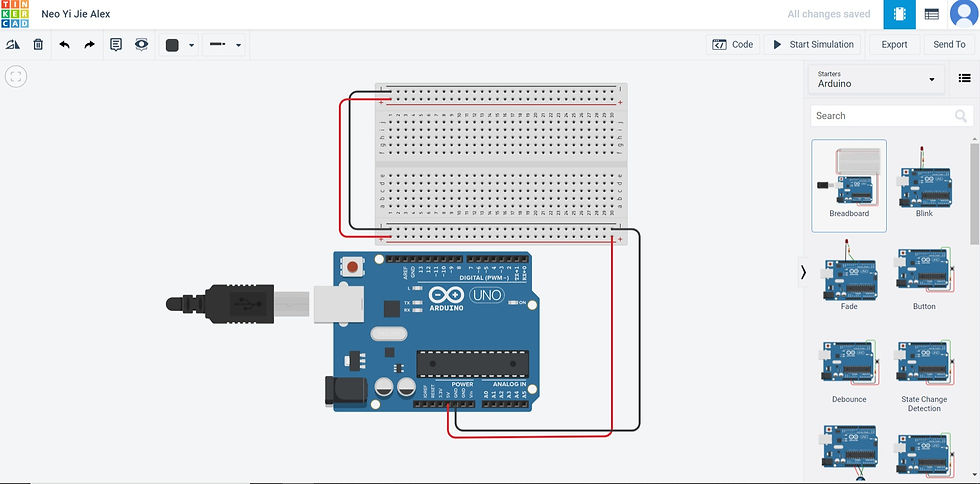
First things first, we prepare the basis of our entire Arduino by selecting Starters Arduino on the top right and pulling out the Breadboard. This shall be repeated before the start of all 4 tasks.
Interface a Potentiometer Analog Input to maker UNO board
and measure its signal in serial monitor Arduino IDE
1. In this first task, change the top right to Components Basic, using the search bar, locate a Resistor, LED, Multimeter, and Potentiometer. Drag them out and put them on the Breadboard as shown in the picture below.
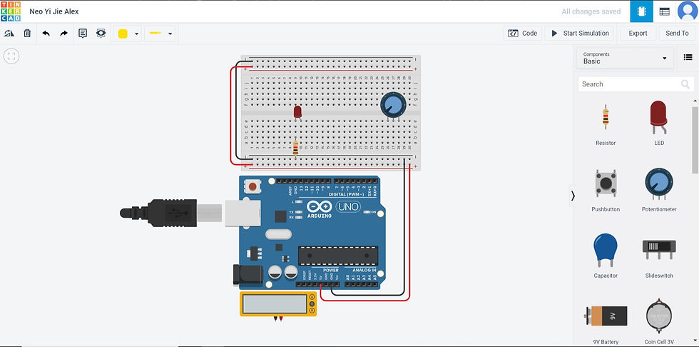
2. My Resistor is set to 100 ohms, and my Potentiometer is set to 1 ohm, the ohms can be set by clicking on the individual components.
3. Now place the individual wire respectively as shown in the picture below.
Yellow wire connecting Pin 13 to D10
Green wire connecting Pin A0 to the red connection point of Multimeter
Green wire connecting Pin A0 to D27
Red wire connecting Positive (+) 28 to D28
Black wire connecting Negative (-) 26 to D26
Black wire connecting Pin GND to the black connection point of Multimeter

4. Next, I shall make the source code that will be used for controlling the microcontroller.
First, I shall set the variable as sensorValue. Depending on how much the Potentiometer is turned, the time delay is set from 0 to 1023 milliseconds depending on how much the Potentiometer is turned. This is sent as an electrical signal to A0 on the microcontroller and then sent to the LED which will repeatedly flash from around 0 to 1023 milliseconds depending on how much the Potentiometer is turned. If the Potentiometer is turned to the left, the delay will be smaller and the flashing will be faster. If the Potentiometer is turned to the right, the delay will be larger and the flashing will be slower.
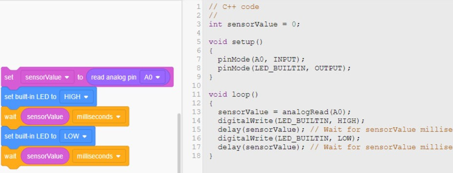
5. The source code can be seen below with the download link to be used in the Arduino IDE. An embedded file and the shared URL link of the simulation is located below also.
Video of Potentiometer Analog Input
Reflection:
For this first task, I had trouble with the resistors as I did not realize that the resistance at first was in kilo-ohms. After changing to ohms, I then process to play with the resistance values to get a resistance value that I'm comfortable with that also shows the brightness of the LED. The Potentiometer wasn't much of a problem.
Interface a LDR to maker UNO board
and measure its signal in serial monitor Arduino IDE
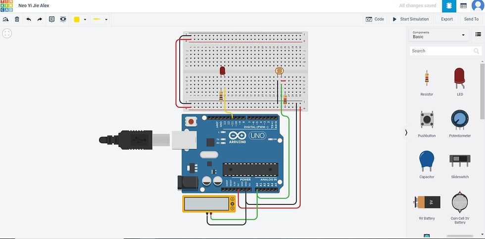
1. Similar to the first task, the first step change the top right to Components Basic, using the search bar, locate two Resistors, LED, Multimeter, and Photoresistor (LDR) . Drag them out and put them on the Breadboard as shown in the picture below. In this case, a resistor will be placed connecting Positive (+) 26 to A26.
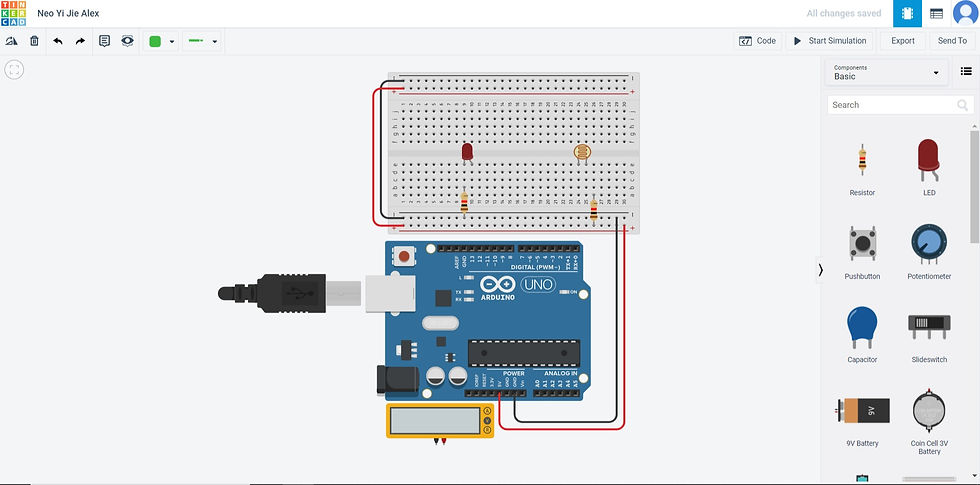
2. The Resistor placed at Negative (-) 9 to B9 is set to 100 ohms, the other resistor place at Positive (+) 26 to A26 is set to 1.5-kilo ohms. The ohms can be set by clicking on the resistors.
3. Now place the individual wire respectively as shown in the picture below.
Yellow wire connecting Pin 11 to B10
Green wire connecting Pin A0 to the red connection point of Multimeter
Green wire connecting Pin A0 to C25
Red wire connecting D26 to D27
Black wire connecting Negative (-) 24 to D24
Black wire connecting Pin GND to the black connection point of Multimeter
4. Next, I shall make the source code that will be used for controlling the microcontroller.
First, I shall set the variable as photosensor. Depending on how much light is shined on the Photoresistor (LDR), the anologyWrite map will set between 0 to 180 depending on how much light is shined on the Photoresistor (LDR). A0 will receive the electrical signal value between 0 to 180 and convert to another electrical signal from between 344 to 1017. This is sent as an electrical signal from 344 to 1017 to the microcontroller and then sent to the LED which will light up at different light intensities depending on how much light is shined on the Photoresistor (LDR). If the light shined on the Photoresistor (LDR) is at low intensity, the anologyWrite map will be set high and the LED will light up brightly. If the light shined on the Photoresistor (LDR) is at high intensity, the anologyWrite map will set low and the LED will light up dimly.
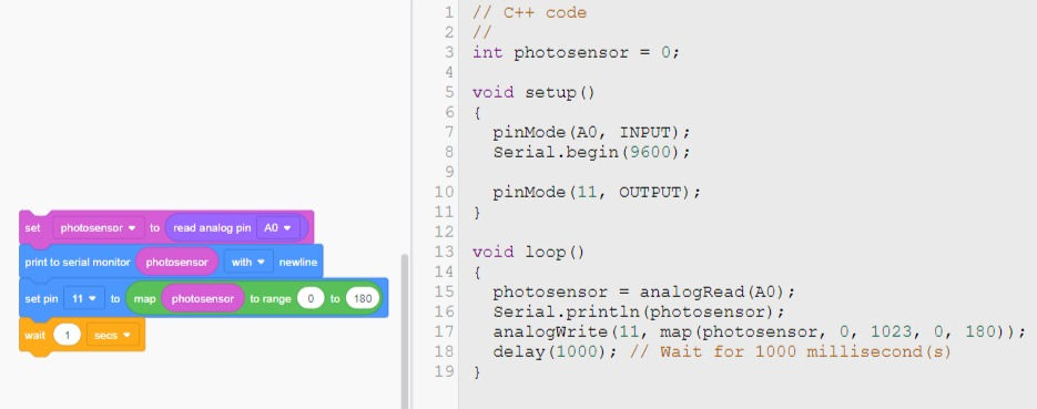
5. The source code can be seen below with the download link to be used in the Arduino IDE. An embedded file and the shared URL link of the simulation is located below also.
Video of LDR (With anologyWrite map range of 0 to 10000)
Reflection:
When making the coding for the Photosensor, I couldn't gauge what would be the range that I would put, so I just went ahead and used the values 0 to 180. As I did the Arduino in real life, the sensor with the range of 0 to 180 wasn't high enough to detect light changes. So I tried at a high-value range of 0 to 50000 and realized the Photosensor was too sensitive. Finally, I used the range of 0 to 10000 and I felt comfortable as it was working without much problem of not being able to detect light changes or too sensitive to light changes.
Interface 3 LEDs (Red, Yellow, Green) to maker UNO board
and program it to perform something (fade or flash etc)
1. Similar to the first task, the first step change the top right to Components Basic, using the search bar, locate three Resistors, three LEDs, and Multimeter. Drag them out and put them on the Breadboard as shown in the picture below.
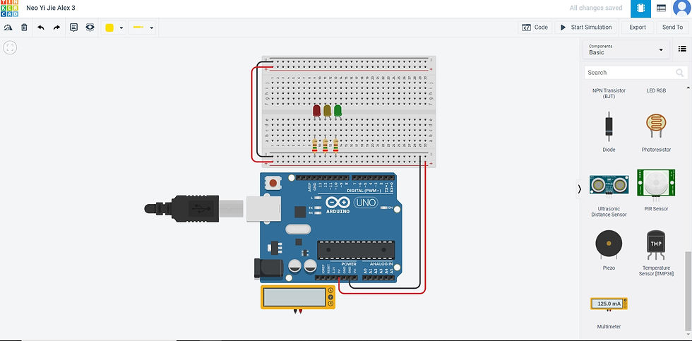
2. All Resistors shall be set to 250 ohms. The ohms can be set by clicking on the resistors.
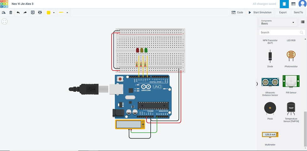
3. Now place the individual wire respectively as shown in the picture below.
Yellow wire connecting Pin 13 to D10
Yellow wire connecting Pin 11 to D12
Yellow wire connecting Pin 19 to D14
Green wire connecting Pin A0 to the red connection point of Multimeter
Black wire connecting Pin GND to the black connection point of Multimeter
4. Next, I shall make the source code that will be used for controlling the microcontroller.
In this case, this code is similar to the traffic light code made during my competency test, but with some add-ons. The delay time is defined as flashingspeed and it is set to 1. A loop is added (for (counter = 0; counter < 2; ++counter) to repeat the following command twice. Similar to how a traffic light works, one LED will turn on at intervals and no two LEDs will turn on at the same time. So starting from 13 (High) -> delay flashingspeed secs -> 13 (Low), 11 (High) -> 11 (Low), 9 (High) -> 9 (Low). This command is repeated twice, and after repeating twice, at the same time, 13 (High), 11 (High), 9 (High). Finally, delay flashingspeed secs and all three will be Low.
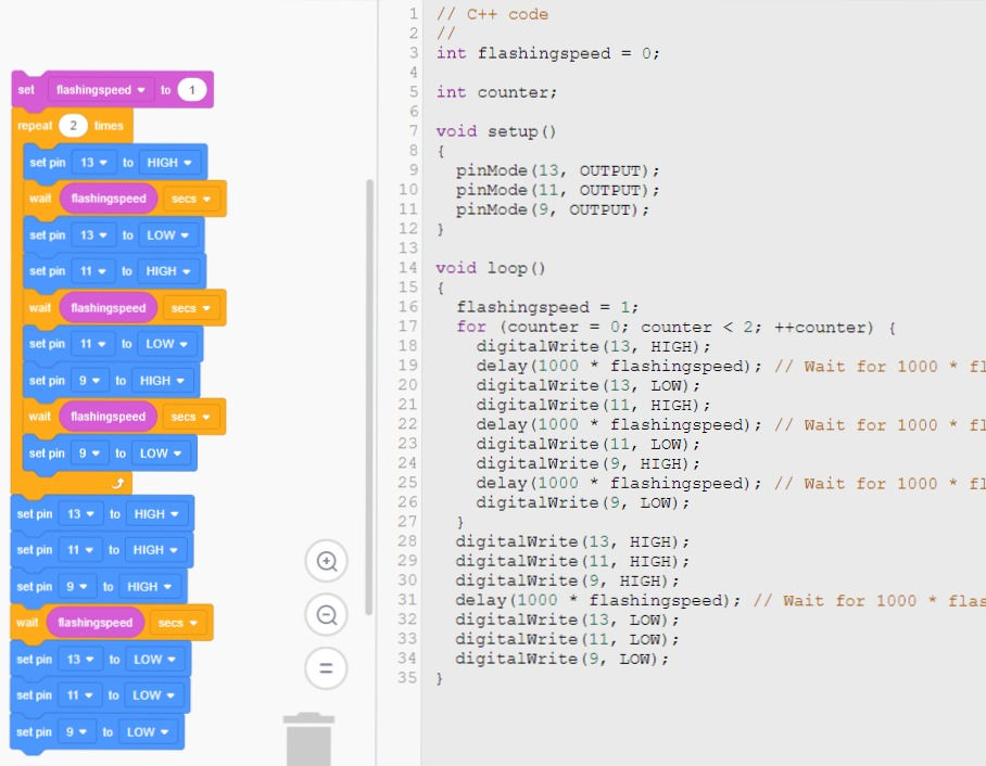
5. The source code can be seen below with the download link to be used in the Arduino IDE. An embedded file and the shared URL link of the simulation is located below also.
Video of 3 LED (Only LED on the microcontroller is working)
Video of 3 LED (Using TinkerCAD)
Reflection:
This was relatively easy as this program was similar to the one from the competency test but with slight changes. However, the problem encountered with the real-life microcontroller was that for some unknown reason, the LEDs on the Breadboard aren't lighting up as expected from the TinkerCAD, but the LEDs on the microcontroller was working, so I'm not sure what is the problem.
Interface the DC motor to maker UNO board
and program it to on and off using push button on the board
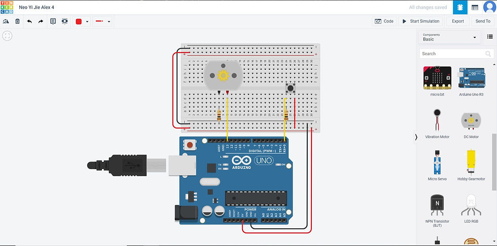
1. Similar to the first task, the first step change the top right to Components Basic, using the search bar, locate two Resistors, and DC motor. Drag them out and put them on the Breadboard as shown in the picture below.
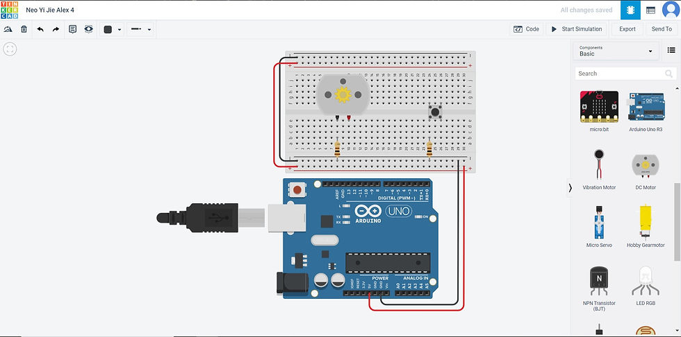
2. All Resistors shall be set to 100 ohms. The ohms can be set by clicking on the resistors.
3. Now place the individual wire respectively as shown in the picture below.
Yellow wire connecting Pin 13 to D10
Yellow wire connecting Pin 0 to D24
Red wire connecting Positive (+) 26 to D26
4. Next, I shall make the source code that will be used for controlling the microcontroller.
The button is defined as button. As the button is pressed in place, it will turn on PIn 0. If Pin 0 is high, Pin 13 will be high and will result in the DC motor to rotate. If the button is l let go, Pin 0 will be low and Pin 13 will be low and result in DC motor stops rotating.
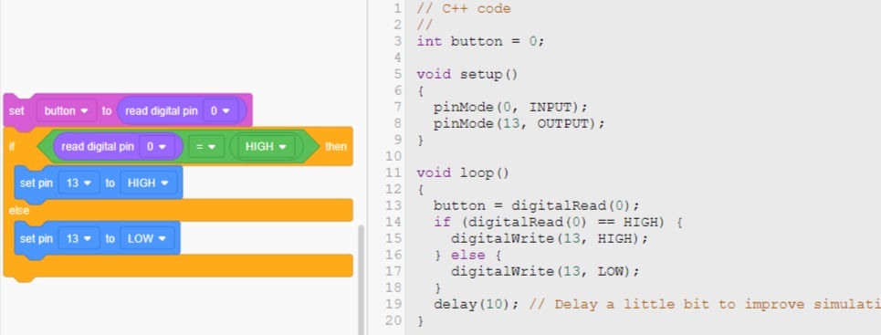
5. The source code can be seen below with the download link to be used in the Arduino IDE. An embedded file and the shared URL link of the simulation is located below also.
Video of DC motor (Using TinkerCAD)
Reflection:
After going through all the previous 3 tasks, doing the DC motor was not that hard after some assistance from youtube tutorial videos.
Overall Reflection:
Overall, this Arduino was real fun as it brought out my curiosity to learn the program. Granted that using TinkerCAD is using blocks that give the ease of coding the program, but the blocks allow me to easily understand the code. There were problems when I was doing the wiring of the microcontroller to the components, which I went ahead and watch youtube tutorials and online forums to figure out my issue. This task issued is extremely useful as it will be extremely useful during my Capstone Project. It is also very interesting as it is very eye-opening of some of the possible inputs that can be used to give out an output, which the output can be anything like from a servo motor to an activated action online in a cloud.
I used to think that Arduino programming is tough and difficult to understand, indeed at first it was difficult but I put in my heart to understand it, it would be a breeze afterward. Now with this new skill, I can see much more possibilities for my Capstone Project.


Comments