COMPUTER AIDED DESIGN - Making of Keyring and Phone Stand
- Alex Neo
- Nov 7, 2021
- 4 min read

Updated: Nov 12, 2021
During last semester's CP5065 Introduction to Chemical Product Design, we learned how to use the Computed Aided Design CAD called Fusion 360. Here are some fun from last year's fun with Fusion 360.
Making of keychain with the basics such as extrude, extrude cut, and text
Combining different parts of files into one assembled file
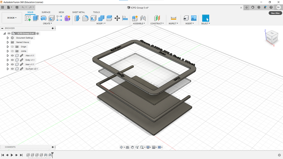
Exploded view of photo frame
Making of the Keychain
For the lesson, we had a recap of the basics of how to use Fusion 360. So I went ahead and made the keychain.
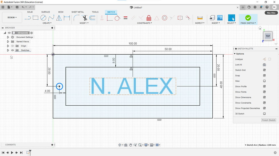
Here are all the dimensions defined by me, which would be the size of the keychain.
Dimension
Outer keychain dimension = 100mm length by 40mm width
Offset dimension = 8mm offset, 84mm length by 24mm width
Keychain hole dimension = 4mm diameter
Text dimension = 10mm height, centered in the keychain
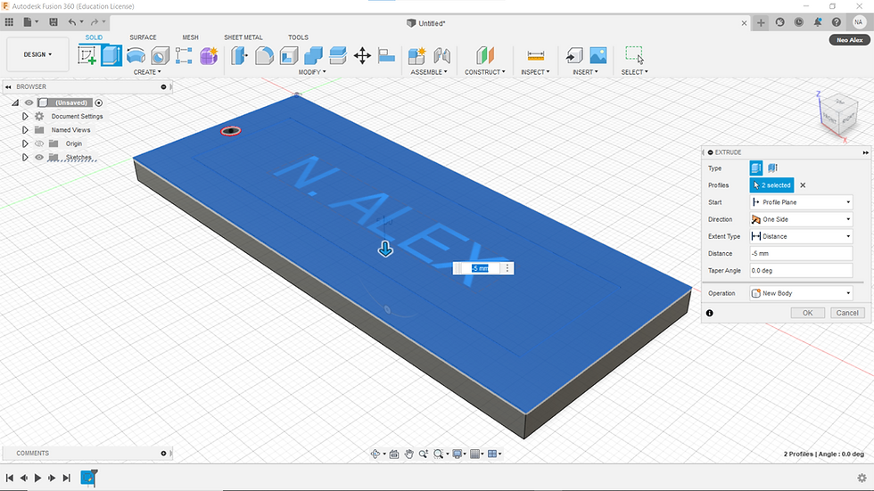
Extrude
All except the keychain hole and text are extruded by 5mm depth.
Extrude Cut
The inner offset of 8mm offset, 84mm length by 24mm width is extruded cut by 2.5mm depth to make a depression on the keychain.
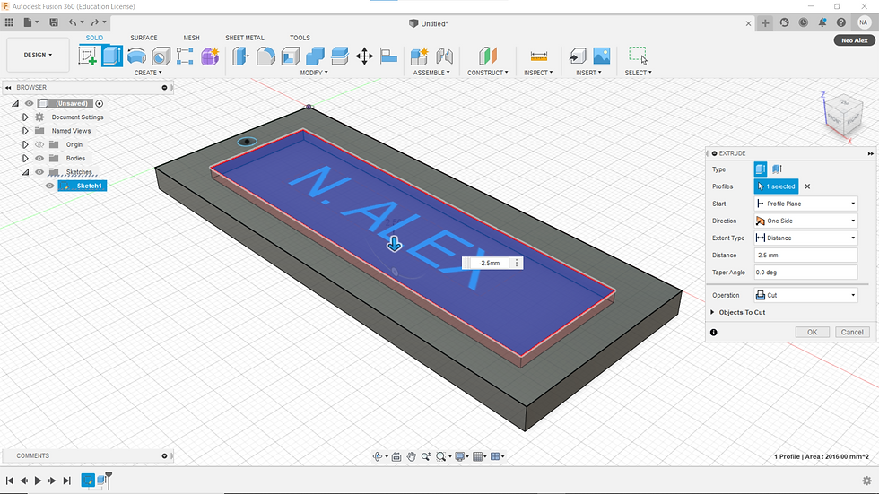
Extrude
The final extrude is for the text by 2.5mm depth.

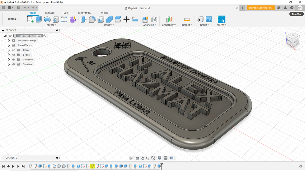
Final Product Keychain (Simple)

Touches can be made on the Final Product Keychain (Simple) to make the keychain look more smooth and nicer. Personalized engraving can also be made on the keychain.
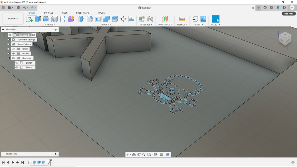
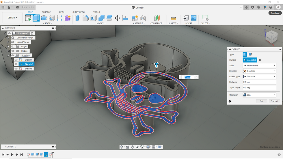
Functions such as Canvas, Fit Point Spline, and Mirror allow customized shapes to be made into the keychain such as this skull.
Filet
First, do 10 mm filet at the outer and the inner edges to allow the keychain to be smoother.
Then do 1 mm filet to do a final smoothing.


Final Product (Personalised)

Final Product (Embedded, Personalised)
Reflection:
My true goal for using Fusion 360 is that I want to translate my skill from one CAD software to another. In this case, from Solidworks to Fusion 360. Even though Solidworks is much more advanced than Fusion 360, Fusion 360 is free for all students and it is also one of the most advanced CAD software out there. I must re-learn, translate and transition to be able to use Fusion 360. I'm stepping out of my comfort zone and went ahead to watch tutorial videos in my free time to be able to use Fusion 360 more efficiently. To me, Computed Aided Design is really fun as my own ideas can be materialized digitally in 3D, once materialized, the idea can be made physically via Laser Cutting or 3D Printing, etc. Fusion 360 is a software that I have to learn that is useful in this module CP5070 as parts can be fabricated but most importantly, rapid prototyping of parts for my Capstone Project can be easily fabricated and tested.
Making of the Phone Stand
With the new knowledge of Parametric Design as shown from my Laser Cutting blog page, we are tasked to design a phone stand using that concept. I decide to get interesting and use Parametric Design more sophistically and ensure that nothing goes wrong.
These are the defined parameters I've defined beforehand and along the way, as I made my phone stand.

Change Parameters
Name/Unit/Expression :
Depth/mm/5 mm
Thickness/mm/20mm
Length/mm/20 mm
HexLength/mm/70 mm
RecLength/mm/80 mm
BaseLength/mm/20 mm
SlotLength/mm/40 mm
WoodThick/mm/5 mm
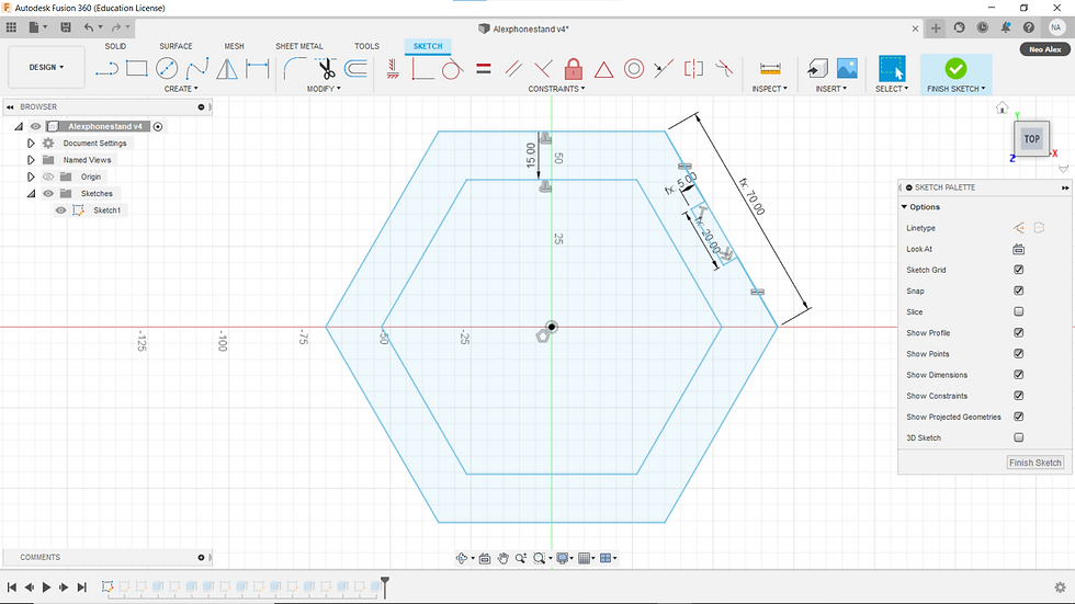
The first thing that I've want to make was a hollow hexagon support. Using Inscribed Polygon, I made a hexagon with the side dimensioned as HexLength (fx: 70.00). The hexagon is then Offset by 15 mm. The hexagon side at the top right is chosen to be the slot that I will make later on. So a slot is made using Line dimensioned Depth (fx: 5.00) and
Thickness (fx: 20.00), the slot is also centered along the length of the HexLength (fx: 70.00) using Equal, so that if the dimension of Depth (fx: 5.00) and Thickness (fx: 20.00) were to change, the slot will remain centered.
Next, I made a base holder to allow the phone to stand on the phone stand. Using 2-Point Rectangle, two rectangles are made with dimensions set at SlotLength (fx: 40.00), WoodThick (fx: 5.00) and BaseLength (fx: 20.00), RecLength (fx: 80.00) respectively. The small rectangle is centered along the length of RecLength (fx: 80.00) using Equal, so that if the dimension of SlotLength (fx: 40.00) were to change, the slot will remain centered.

Next, I made the slot piece that will joint both the hollow hexagon supports and rectangle base. 2-Point Rectangle, it is dimensioned at Thickness (fx: 20.00) and Length (fx: 20.00).

Lastly, I've made a rectangle base for the phone to rest on. For this piece, it was the most complicated as this piece has the most defined measurements under Change Parameters, this means changing anything on this piece would affect the other pieces. Using 2-Point Rectangle, the length is the rectangle is dimensioned at half-length at HexLength (fx: 70.00) and RecLength (fx: 80.00) and using Equal, both half-lengths are set to equal. This means that I've made the total length of the rectangle to be twice on one side of the hollow hexagon support. A slot has to be made so that the rectangle base can be attached to the hollow hexagon support. The slot is made using Line dimensioned at Length (fx: 20.00) and Thickness (fx: 20.00). The slot is centered along the length of HexLength (fx: 70.00) using Equal, so that if the dimension of Thickness (fx: 20.00) were to change, the slot will remain centered.

Finally, all the sketches are Extruded by 5mm.
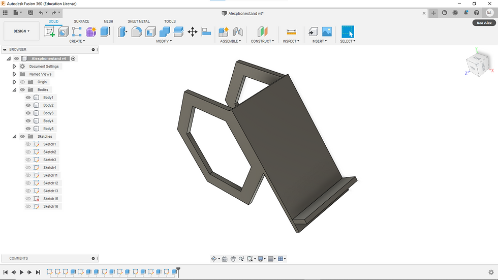
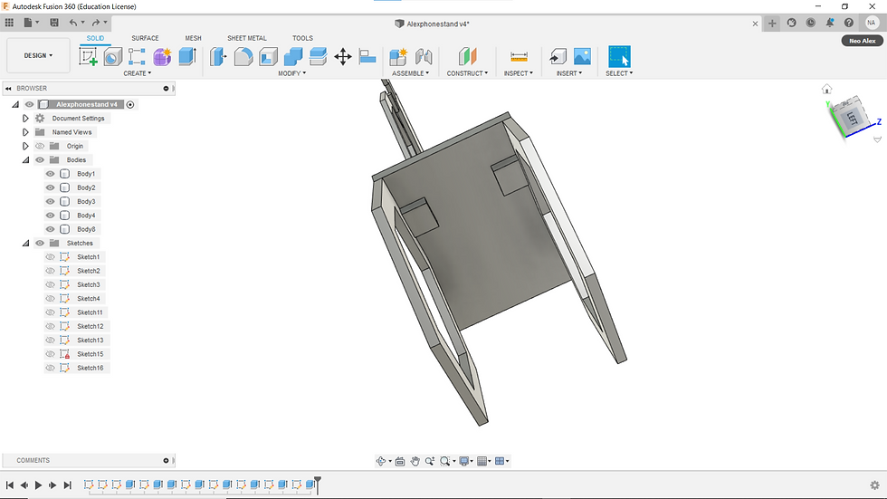
This is the finalized phone stand, both in its pieces form, and its 3D completed built form.
Final (In pieces form)

Final (3D completed built form)
Final (3D completed built form with slot pieces exposed)
Final (Embedded, In pieces, form and 3D completed built form)
Reflection:
The goal of this task is to go beyond our comfort zone and create our own phone stand with our own design by implementing Parametric Design that can be used for Laser Cutting. To me this task is important for me to be more familiarized and comfortable with using Parametric Design. With it, I was able to make this phone stand with more parts that allow changing of parameters to be easily and quickly made. Hence, this task allows me to go even further of the complexity of making products, but most importantly this is extremely useful for me when making of my product during Capstone Project as this Parametric Design saves much time for making the product for testing. Before the introduction of Parametric Design, I had never used this concept during my time of using Solidworks, and I thought of it was a waste of time, however, seeing it now it has the huge potential to save much time for me during Capstone Project, I'm grateful of learning it.


Comments