LASER CUTTING - With Parametric Drawing
- Alex Neo
- Nov 8, 2021
- 6 min read

Updated: Nov 16, 2021
In this lesson, we were taught how to use Fusion 360 and make rapid changes to dimensions at moment's notice. Using the function called Parametric Drawing, we can make quick changes to multiple objects that share the same dimensions that are already defined. Then using Coreldraw Laser Cutting, I can produce the product that was drawn in Fusion 360. Sizing errors that are defined under Changes Parameters can be changed easily within minutes and testing runs of laser cutting of the product can be carried out for trial and error. In my blog, I will only show how I made the long piece with semicircle ends on each side which for easy identification we will call it Long. The hexagon and triangle I will not show step by step as explaining step by step will take too long and they are much relatively easy to make.
Before starting any drawing, locate Change Parameters under the expanded taskbar of Modify.


<------------- Here
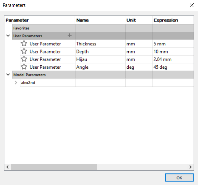
Parameters table would be shown. Before any work is done the table would be empty.
Besides User Parameters, the plus option is selected to allow me to define a set dimension by giving it a name. This not just allows measurements of length to be defined, other units such as degree, power, energy, etc can also be defined.
For instance, I set 4 defined dimensions that I can change dimension easily later by reentering the Change Parameter menu.
Name/Unit/Expression :
Thickness/mm/5 mm
Depth/mm/10 mm
Hijau/mm/2.04 mm (This dimension was set by my group due to a certain constraint we face for one of our pieces.)
Angle/deg/45 deg


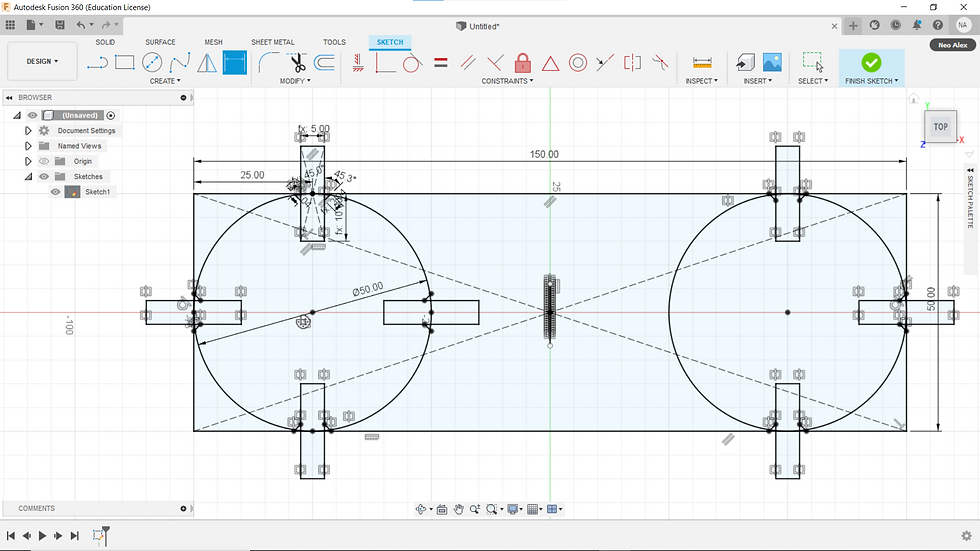
We decided to make 3 different pieces, a triangle, a hexagon, and a long piece with semicircle ends on each side which for easy identification we will call it Long. We started making the Long.
Basic dimensions of the Long:
Length = 150 mm, Width = 50 mm, constructed using a Center Rectangle with the 0 point XYZ axis as its center.
A circle is created using a 3 Point Circle to make one circle on the left side inside the Center Rectangle. To ensure the circle is perfectly at the edge of the rectangle, ensure to place 2 Tangent at the length and width of the rectangle.

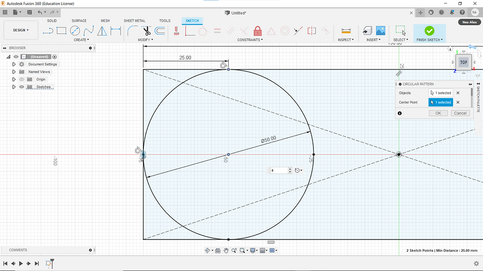
Create a point at the edge of the circle at a distance of 25 mm. Then using Circular Pattern taking the centre of the circle as the centre point to duplicate the points 4 times around the circle.
Here's where the 4 defined measurements are going to be used to assist me later on during Laser Cutting. Using Sketch Dimension, I can name the dimension accordingly to the set names of dimensions at Change Parameters. For instance, by changing the selected dimension with the name Thickness, the dimension will be set to 5mm as stated at Change Parameters, the name on the dimension will appear as fx: 5.00. I went ahead and did for the rest of the values as stated below.
Thickness/mm/5 mm (fx: 5.00)
Depth/mm/10 mm (fx: 10.00)
Hijau/mm/2.04 mm (fx: 2.04)
Angle/deg/45 deg (fx: 45.0°)
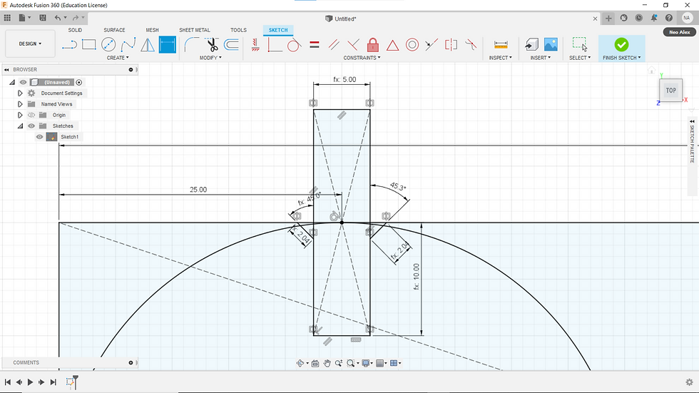
Then using Circular Pattern again, highlighted the parts I want to replicate around the circle.

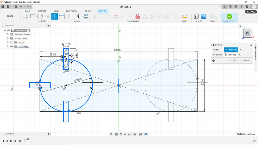
Using Mirror, the highlighted parts are replicated onto the other side of the rectangle. Ensure there are no free moving sketches, for my case was the replicated circle has to be Tangent with the width of the rectangle. If there are no free moving sketches, the sketch outline will be black in color, if not it would be blue.
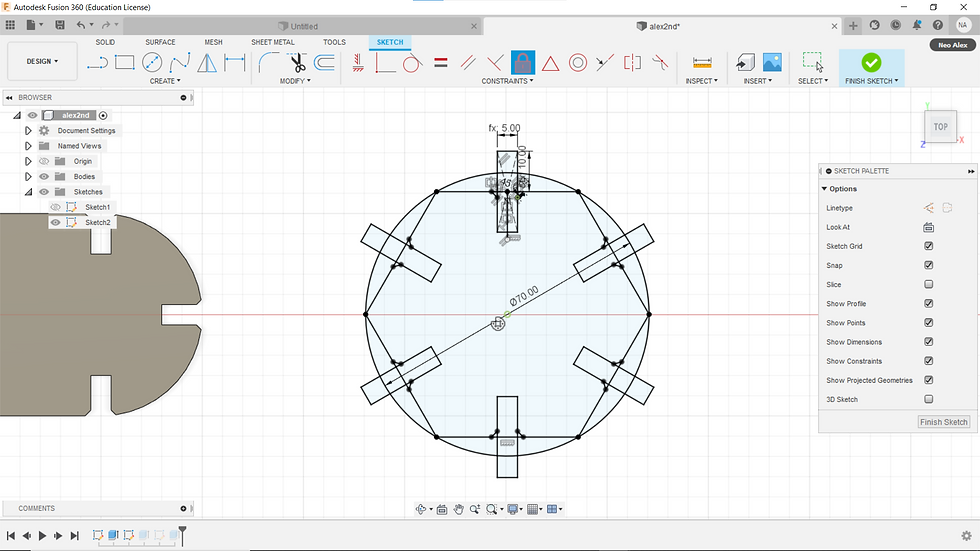
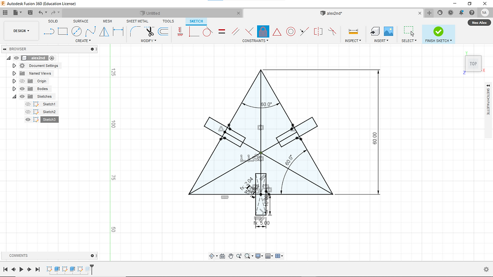
The hexagon and triangle are much easier to make so I'll only show the sketch dimensions of them here because explaining step by step will take too long and they are much relatively easy to make.
All the sketches are then Extruded by 10 mm.

Final (Embedded, In pieces, form and 3D completed built form)
With the pieces made, we can now proceed with the Laser Cutting, With the combination of Parametric Drawing and Laser Cutting, trial and error of the Laser Cutting sizing can be adjusted in a matter of minutes.
Here's an anatomy of how Laser Cutting works
A Laser Resonator will send light with the help of a Focusing Lense and Laser Gas, the Laser light emitted will be focused to a single point which much of the light energy will become heat energy, which will be hot enough to cut vinyl, acrylic, and wood. The intensity of the heat energy is dependent on the focal length, which how much light energy will be focused into one small area.
The main materials that are suitable for laser cutting are:
Acrylic: Up to 5mm
Wood: Up to 6mm (Plywood, natural wood, MDF)
Cardboard
Paper
There are other materials such as vinyl, etc are also suitable for Laser Cutting.
Using the SOP made by my group
Startup:
1. Locate and switch on the air compressor (at the back of the red switch)
2. Switch on the fume extractor (green button)
3. Turn on the laser cutting machine by pressing the “on-off” switch (black) on the right side, wait for it to finish initializing.
4. Proceed to the workstation.
Operating Laser cutter and Corel Draw:
1. Laser cutter hatch must be fully enclosed (do not slam the cover)
2. Ensure there are LED lights on the interlock system (do not assume there’s no interlocking light or spoils).
3. Open file to select the job that is needed to be laser cut
4. Once the design has been done, click on the ‘form icon’ and click ‘print’
5. Turn on ‘auto focus’
6. Click on the engraving tab (green color) and select ‘import material drawing’
7. Input thickness ‘3mm’
8. Do steps 5-6 for the vector tab (red color)
9. Turn on ‘air assist’ for both the engraving and vector tab
10. Check on the machine panel to ensure the correct job name and also the estimated timing
11. When ready, press ‘go’
12. Once the operation is done, wait for 1 min to let the material cool down
13. Inform the staff on duty that you have finished laser cutting
14. Open the hatch and collect the material
15. Collect any usable material and put them in the recycling bin
Shut down:
1. Proceed to switch off the laser cutting machine.
2. Then switch off the fume extractor.
3. And then switch off the air compressor.
4. Proceed to do housekeeping
Safety:
● Do not wear anything around your neck.
● Those with long hair, tie your hair up. - Boys with long fringe, clip it up.
● The precaution(s) to take in using laser cutter machine
- Do not put your head inside if the cover is just halfway open.
- Do not slam the cover (the interlocking light will disappear).
- Ensure that the 2 interlocking lights on the side are on.
- Do not lean your body against the laser cutting as this will impair your vision
Here's a video of the Laser Cutting cutting the workpiece
Here's the result of our first run, however, I only have a part of our first run.

The problem faced here was that we took the wrong size of wood, it being a smaller size as compared to the notch that was made in Fusion 360.
On the second run, we changed the wood that is being cut from 3mm to 5mm and went ahead to cut our second run. One the second run with the defined measurement of Thickness/mm/5 mm (fx: 5.00) under Parametric Drawing with 5 mm thick wood, we cut out 2 of the hexagon pieces, to try and see if the hexagons would fit each other. As it turns out the pieces are slightly too loose due to Kerf. This is due to the slight amount of extra wood that is burnt off by the Laser Cutter known as Kerf
Illustration of Kerf

Kerf is the material that is being cut by the laser cutter. However, the kerf is uncontrollable and would burn more excess material away than is required. This means depending on the location of the cut, the cut-out piece would end up being slightly smaller, spaces in between pieces will be larger. In my case, the slot cut out is slightly too big.
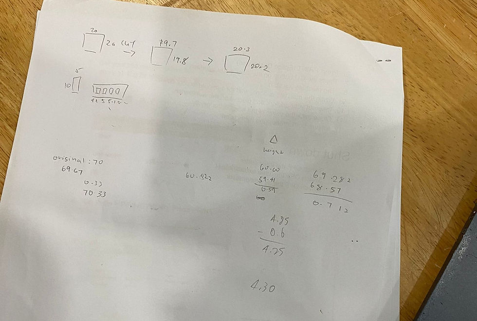
Using a Vernier Caliper, we adjusted according to and took the extra burnt away wood measurement and I changed the measurement of Thickness/mm/5 mm (fx: 5.00) under Parametric Drawing to a smaller value.
Using Vernier Caliper we found the actual cut-out area of different parts of the cut-out piece. Next, we write down all the cut-out values and obtain the different kerf cuts values and get an average kerf value cut-out. Hence, I changed the measurement of Thickness/mm/5 mm (fx: 5.00) under Parametric Drawing to 4.712 mm. Kerf was 4.712 mm.

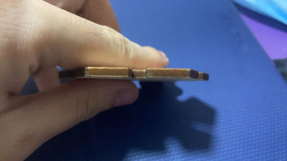
This is the result of the Third run.

It was a tight fit but it was perfect. I am happy with the pieces.
During the changing of the Parametric Drawing, there was some issue faced when the measurements changed, but I managed to change them properly without any hiccups.
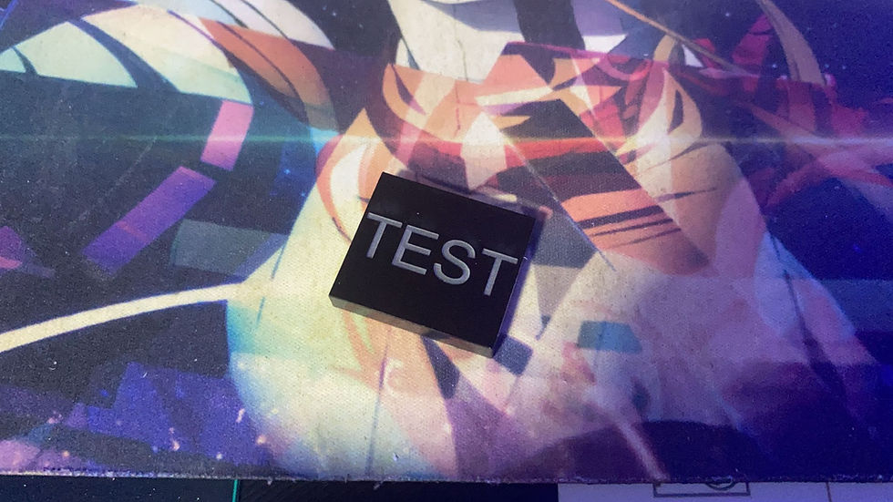
I also took the competency test for Laser Cutting, and funny enough I'm the only one that failed on the first try hahahahaha wkwkwkwkwk. After a reteaching by Mr Ting, I managed to pass my competency test and here's the result of it.
Competency Laser Cutting test
Reflection:
There was a hiccup I encountered when using Parametric Drawing when using it for slightly more complicated drawings, in which the dimension will go haywire when the defined dimension was changed. I also did fail my first run of competency test as I wasn't really familiar with the CorelDraw and Laser Cutting and for me, I do take a long time than others to learn. With Laser Cutting and Parametric Drawing, it is useful for me when making my product during Capstone Project as this Parametric Design saves much time for making the product for testing.


Comments